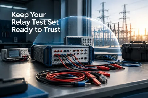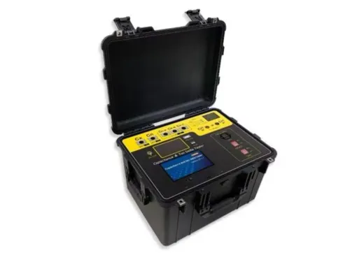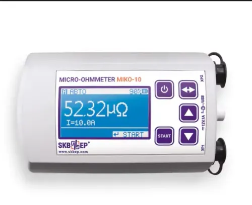


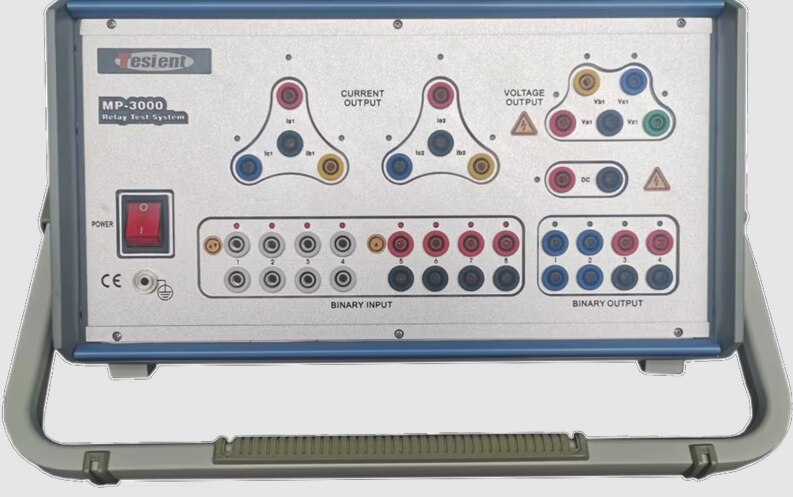
The work starts with approved settings, wiring records and a safe isolation plan—not with current injection. By the end, you will know how technicians test relay elements, protection logic, communications and the complete trip circuit, and how Mumbai site conditions affect the sequence.
Key takeaways
- Confirm relay identity, firmware, settings, CT/VT data and trip logic before injection.
- Record pickup, operating time, trip output, binary input and communication results.
- Use IEC 61850 test methods to verify GOOSE and sampled-value performance.
- Plan Mumbai testing around access, isolation, safety permits and approved commissioning documents.
What must be checked before relay injection begins
Injection starts only after the technician proves that the installed relay and its circuits match the approved design. Compare the relay model, firmware, serial number, approved setting file and selected setting group with the latest single-line diagram, CT and VT data, trip matrix, communications drawings and breaker-failure logic.
Check these field details before connecting the test set:
- Confirm CT ratios, star-point location, phase identification, secondary earthing, polarity, continuity and loop resistance or burden where required.
- Confirm VT ratios, phase identification, fuse or MCB wiring and circuit continuity.
- Verify interlocks, trip links and the expected breaker-failure and communications responses.
| Document or control | What to confirm | Failure prevented |
|---|---|---|
| Latest protection drawings | Single-line, CT/VT, trip matrix and communications logic match the panel | Testing the wrong circuit or scheme |
| Switching and isolation plan | Isolation boundary, work permit, test position, outage window and trip-output arrangement are approved by the asset owner | Unauthorised energisation or breaker operation |
| CT test block | CT secondaries are shorted before relay leads are removed | Dangerous CT secondary overvoltage |
| Trip circuit arrangement | Trip outputs are isolated or routed through an agreed test path | Secondary injection tripping a live breaker |
Never open an energised CT secondary. Mumbai does not define one universal relay test system procedure in Mumbai: transmission, industrial, metro, commercial and distribution sites follow the owner’s protection philosophy and the applicable licensee requirements.
The relay test system procedure from connection to sign-off
1. After isolation, verify the test set’s protective earth and inspect every current, voltage and binary lead for damaged insulation, loose plugs or incorrect labels. Connect current and voltage leads to the approved relay test block or relay terminals without disturbing an energised CT secondary circuit.
2. Assign binary inputs to relay start, trip, alarm and breaker auxiliary contacts. Check binary outputs against the intended trip, block and reset commands, including interposing or lockout relay signals where included in the test arrangement.
3. Load the approved test file and confirm nominal frequency, phase rotation, CT and VT scaling, setting group and channel assignments. Run a low-level measurement check before applying fault quantities, then establish a pre-fault state with the expected voltage, current and phase relationships.
4. Apply defined fault current, voltage, phase angle and frequency values. Record pickup, operate, reset and dropout times, along with relay LEDs, display flags, event records, binary outputs, annunciation and SCADA points where included. Directional, differential and distance tests require coordinated phase quantities, not current alone.
5. Remove all injections after testing, restore CT and VT wiring, return setting groups and trip links to their approved positions, clear test flags and recheck the isolation boundary. These relay testing steps for commissioning in Mumbai end with a supervisor comparing results with acceptance limits and signing the test sheet.
Record the relay serial number, firmware, test-set calibration status, defects and corrective actions; “relay tested OK” is not an adequate record.
Which protection functions are injected, and what the results prove
A protection relay testing process in Mumbai turns each enabled function into defined inputs, thresholds, times and outputs. Secondary injection proves relay measurement, element pickup, timing, programmed logic and assigned outputs; it does not prove the entire primary circuit.
- Overcurrent: inject pickup, instantaneous or definite-time faults, inverse-time points and reset or dropout values. Check phase selection, curve family and time multiplier.
- Earth fault: apply residual or zero-sequence current and verify pickup, timing and trip logic.
- Directional: control polarising voltage, current magnitude and phase angle to confirm the operating boundary.
- Differential: apply matched operating and restraint currents.
- Distance: test zone impedance points, resistive reach and directional boundaries.
- Under/overvoltage and frequency: run controlled ramps through thresholds, delays and recovery values.
- Autoreclose: verify initiation, dead time, reclaim time, lockout and 52a/52b indications.
- Installed schemes: test negative-sequence, intertrip, permissive, blocking, breaker-failure, busbar and transformer differential logic.
The results must distinguish what each method proves:
| Method | Proves | Does not prove |
|---|---|---|
| Secondary injection | Relay elements, logic, timing and assigned outputs | CT or VT wiring, primary path or breaker operation |
| Primary injection | CT ratio, polarity, saturation and primary current path | Complete relay logic or scheme behaviour |
| Circuit or end-to-end test | Trip circuit, interposing relays, supervision and terminal-to-terminal logic | Nothing beyond the tested arrangement |
Neither method alone proves VT wiring, trip-coil operation, breaker mechanism, trip-circuit supervision or complete scheme behaviour. Use circuit and, where required, end-to-end tests for those checks.
How numerical and IEC 61850 relay tests differ
A numerical relay test begins with configuration, not fault injection. Upload the approved setting group and verify CT and VT ratios, nominal frequency, phase sequence, vector-group compensation, time-current curve, IEC 60255 element identifiers and binary I/O mapping.
Test points then confirm measured quantities, element flags, operate times, event records and logic during normal operation and abnormal conditions.
| Test focus | Numerical relay | IEC 61850 substation |
|---|---|---|
| Inputs | Inject current and voltage through approved test connections | Validate Sampled Values from the merging unit |
| Logic | Check binary start, trip, alarm, block and reset mapping | Check logical nodes, datasets, quality bits and SCL configuration |
| Communications | Test relay indications and event records | Verify GOOSE publication, subscription, VLAN settings and time synchronisation |
| Failure response | Apply VT loss, DC loss, communications failure, trip-circuit failure and blocked protection | Confirm communication-loss behaviour, fallback or blocking logic specified in the approved scheme |
| Output path | Confirm binary outputs operate as assigned | Confirm the receiving relay or physical output responds to each published status or trip message |
A copper binary check cannot prove a Sampled Value stream, GOOSE supervision or a digital trip path. Test both sides of every transaction: the transmitting relay must publish the correct message, and the receiving function must act correctly.
For line differential, permissive, blocking or direct-transfer-trip schemes, use synchronised test sets at separate terminals. Measure channel latency and compare internal-fault operation with external-fault restraint. The approved scheme defines whether communication loss alarms, blocks protection or enables a fallback trip.
How to choose the test system and plan Mumbai site execution
Choose the test system by scheme complexity, not maximum current alone. Compare maximum current and voltage, phase-angle accuracy, frequency range, output burden, DC binary inputs and outputs, ramp and ramp-rate control, transient playback, and independent channels.
| Scheme | Required capability | Selection implication |
|---|---|---|
| Single-element overcurrent | Current output, binary timing, ramps | Fewer outputs can suffice |
| Directional, differential or distance | Coordinated voltage and current, accurate phase angle, matched channels | Control polarising, restraint, impedance and boundary points |
| Multi-terminal or multi-circuit | Six-phase or larger independent output | Separate terminal, restraint and polarising quantities without artificial sequencing |
| Digital or transient-dependent relay | Waveform, timing and communication reproduction | Confirm IEC 61850, transient playback or the relay’s specified method |
Verify waveform shape, timing and communication compatibility before booking the equipment. Myriad Industrial Solutions LLP can help match channel count and commissioning conditions to the scheme, but the asset owner’s approved test plan governs.
At Mumbai sites, check the 230 V AC supply, protective earth, dry test connections, coastal contamination, monsoon moisture, switchgear-room clearance, long lead routes and temporary cable protection. Arrange permits, access windows, isolation boundaries and the Maharashtra utility or industrial owner’s outage schedule; a procedure accepted by one owner may not apply to another.
The relay test system for testing process in mumbai record must identify the relay serial number, firmware, setting group, test-set model and calibration status, injected values, phase angles, frequency, operate times, binary mapping, limits, defects, corrective actions and restoration checks. “Relay tested OK” is not enough for fault investigation.
Related products
 | Protection Relay Test System CRA160LHi-A Three Phase Automatic Relay Test Set (AC-Mains, Extended 4x300V Voltage) CRA160LHi-A Three Phase Automatic Relay Test Set (AC-Mains, Extended 4x300V Voltage) The CRA160LHi-A Protection Relay Test Set is a premium,... View product → |
 | Protection Relay Test System CRA160Hi-A Three Phase Automatic Relay Test Set (IEC 61850 Digital Smart Grid Tester) The CROXS CRA160Hi-A is an automatic, secondary injection relay test system designed for digital substations, generation plants, and high-voltage... View product → |
Frequently asked questions
What must be checked before relay injection begins?
Verify the relay model, firmware, serial number, setting file, active setting group, single-line diagram, CT and VT data, trip matrix, communications drawings and breaker-failure logic.
What does a relay test system procedure include?
The procedure covers safe isolation, wiring and polarity checks, test-system configuration, injection, pickup and timing tests, trip verification, result recording and sign-off.
Which protection functions are injected during relay testing?
Tests can inject functions such as overcurrent, earth fault, differential, distance, under- or overvoltage, frequency, auto-reclose and breaker-failure protection.
How do numerical and IEC 61850 relay tests differ?
Numerical relay tests use physical current, voltage and binary connections, while IEC 61850 tests also verify digital GOOSE messages, sampled values and station-bus logic.
How should you plan relay testing at a Mumbai site?
Select a system with suitable current, voltage, binary, timing and communications capabilities, then coordinate permits, outages, access, drawings, safety controls and client sign-off.
Related products
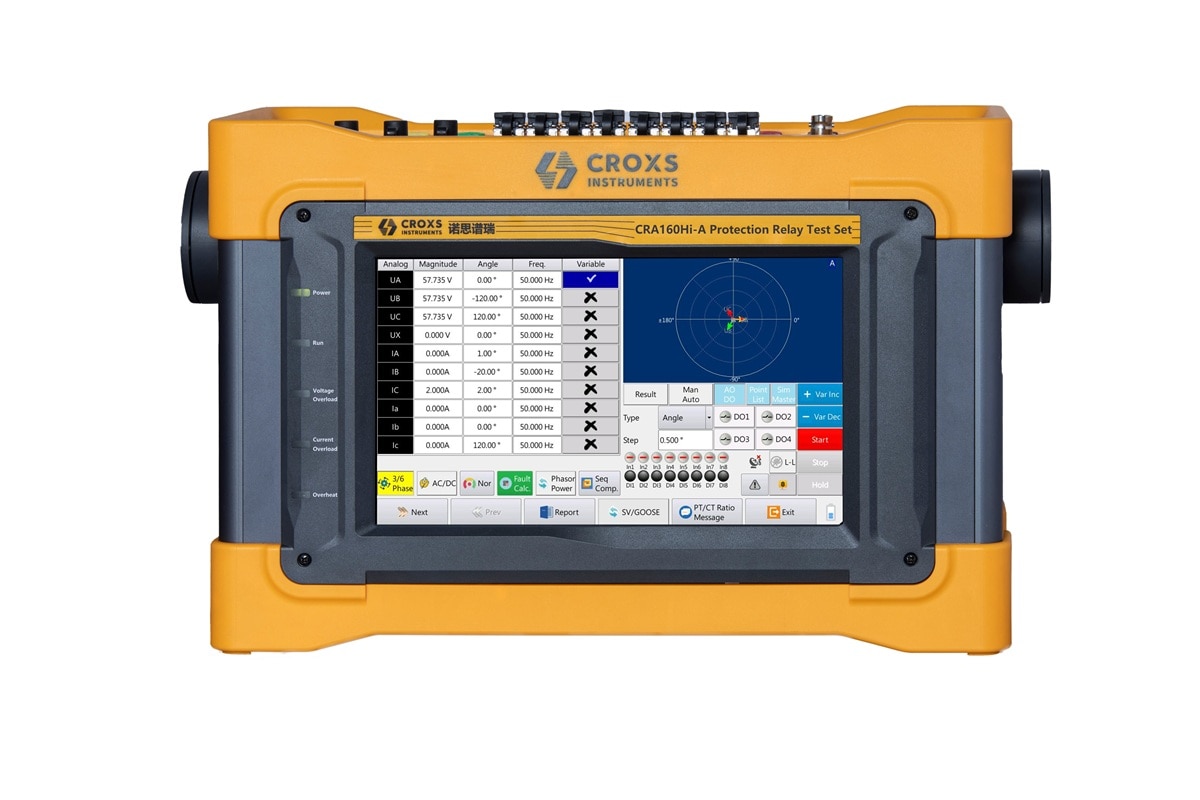 | Protection Relay Test System CROXS Advanced Protection Relay Test System (High Accuracy) Myriad Industrial Solutions LLP offers professional-grade protection relay test systems engineered for electrical substation commissioning,... View product → |
 | PRODUCTS TESIENT MPF300 PORTABLE RELAY TESTER INDIA Tesient MPF300 - 3-phase relay tester: 3×40A (100A parallel), 4×300V, touchscreen, 13 modules, 0.1%... View product → |
 | PRODUCTS The MP3000A Universal Relay Testing System is a state-of-the-art solution engineered for precision, reliability, and efficiency in relay testing. View product → |
 | PRODUCTS Three phase automatic Relay test set Six Phase Protection Test System The powerful three-phase relay test set MP3000A is designed for multipurpose field test and commissioning... View product → |