


Plotting Distance Relay R-X Curves Directly from Relay Setting File
By Sunildatt Limaye
Myriad Industrial Solutions LLP, Mumbai
Specialist Supplier of Secondary Injection Test Kits (Tesient, CROXS) & Protection Testing Solutions
Series Note:
This publication is the second part in our technical engineering series on numerical relay interoperability and open testing workflows. To see the preliminary mathematical foundation and parameter mapping, please review:
The Practical Field Challenge on Site
During commissioning and testing of numerical distance relays (such as Alstom / Schneider MiCOM, Siemens SIPROTEC, ABB, or GE), testing engineers on site frequently face an unexpected delay:
-
Parameter Export vs. Graphical Display: Relay software offers an option to export settings in
.xrioor.rioformat. However, when an engineer imports this raw export into secondary injection test software, the software often cannot draw the characteristic. It shows an empty screen or an "Insufficient information" message. The reason is technical: the raw export is merely a database list of setting registers and OEM internal formulas. It does not supply the ready boundary coordinate points (R, X) required by graphical test engines to plot the quadrilateral tripping polygon. -
Template Availability: Test software typically relies on dedicated, pre-built relay templates to translate these registers into visual boundaries.
-
Shutdown Delay: When the specific template is not readily available on the site laptop, testing teams have no choice but to calculate reach boundaries and fault-loop impedances manually. Calculating multi-zone reaches, line angle tilts, and resistive blinders by hand takes hours per feeder bay during valuable shutdown time.
The Solution: Direct Settings-Based R-X Reconstruction
All tripping boundaries of a numerical distance relay are already governed by the figures inside the relay setting sheet: positive sequence reactance reach (X), line impedance angle (θ), phase and ground resistive reaches (Rph, RG), directional lines, and reverse offset reaches.
By reconstructing the boundary coordinate geometry directly from these setting values, raw setting files are converted into ready-to-test, native templates across modern test platforms:
-
Tesient Relay Library Templates: Fully configured with discrete fault loops and boundary definitions, ready for immediate pick-up reach and timing tests.
-
CROXS Test Templates: Mapped with all active forward and reverse quadrilateral zones, directional cuts, and line replica vectors.
-
Megger RTMS & OMICRON Compatible Templates: Formatted so that the file opens cleanly inside the impedance test screen without parsing errors, syntax warnings, or manual coordinate adjustments.
Site Verification Across Different Test Software
To verify that the reconstructed characteristic matches relay setting values with mathematical accuracy, a real-world transmission line setting file (MiCOM P545, Setting Group 1) was processed and verified across different test software environments:
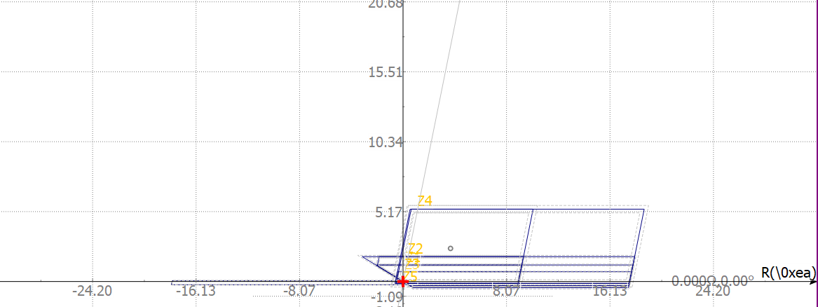
Figure 1: CROXS Testing Software — Full Quadrilateral Mapping
Technical Check: As soon as the file is loaded, CROXS immediately renders all forward zones, the reverse zone, and the transmission line vector at 78.0° without any manual coordinate entry on site. Forward reactive reaches align with the setting sheet: Z1 = 1.25 Ω, Z2 = 1.88 Ω, and extended reach ZP = 5.47 Ω (with top reactive cut ceiling at X = 5.35 Ω).
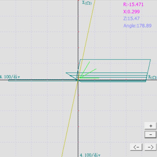
Figure 2: MPWIN Software — Phase-to-Earth (Fault L1–E) Boundary Check
Technical Check: The line replica vector extends at 78.0° into Quadrant 1, matching the line angle. The top reactance line of all forward zones remains flat (0° tilt), consistent with standard MiCOM quadrilateral settings. The right-side resistive boundary widens to account for earth fault resistance governed by the RG parameter.
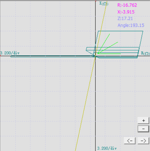
Figure 3: MPWIN Software — Phase-to-Phase (Fault L1–L2) Boundary Check
Technical Check: Both the forward directional cut line in Quadrant 1 and the reverse boundary slope in Quadrant 3 align as per directional settings. Comparing Figure 3 with Figure 2 confirms that the phase-to-phase loop terminates at a tighter resistive boundary (Rph) than the ground fault loop.
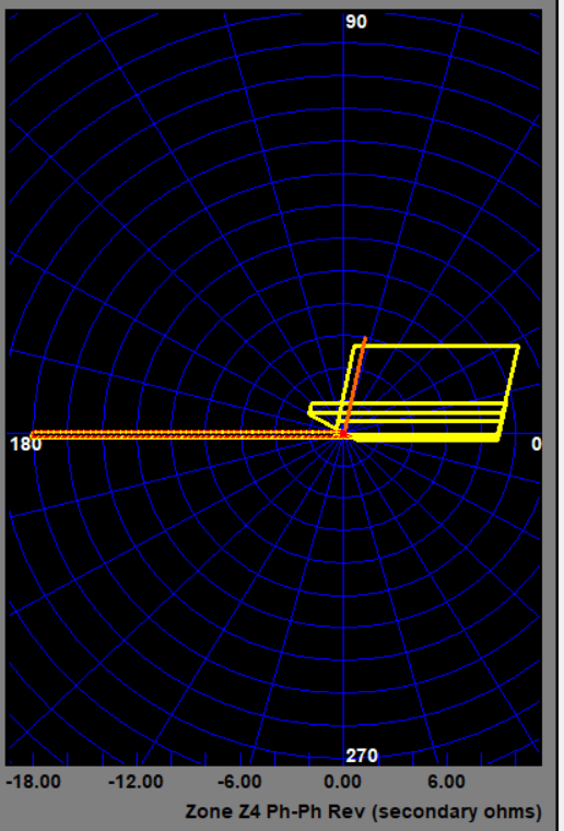
Figure 4: Megger RTMS / PowerDB — Zone Z4 Phase-to-Phase Reverse
Technical Check: Opens directly into the RTMS Click-On-Fault test screen with zero format errors. It accurately plots the reverse quadrilateral zone (Zone 4) extending along the negative resistance axis up to −18.00 Ω without polygon distortion.
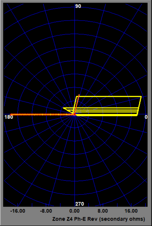
Figure 5: Megger RTMS / PowerDB — Zone Z4 Phase-to-Earth Reverse
Technical Check: Renders the complete reverse quadrilateral zone along the negative resistance axis cleanly up to −16.00 Ω while maintaining identical forward zone stack alignment.
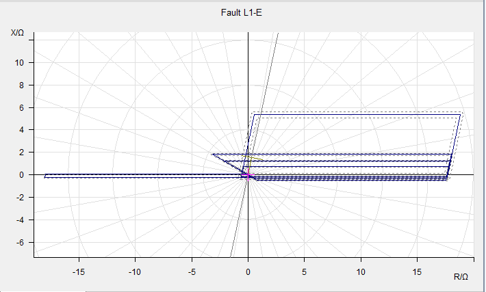
Figure 6: OMICRON Test Universe — Phase-to-Earth (Fault L1–E) Loop
Technical Check
Technical Check: The forward quadrilateral widens up to R ≈ 18.00 Ω, correctly displaying the ground fault loop expansion due to the 30 Ω RG setting. The flat reverse strip (Zone 4) extends beyond -18 Ω horizontally on the negative resistance axis.
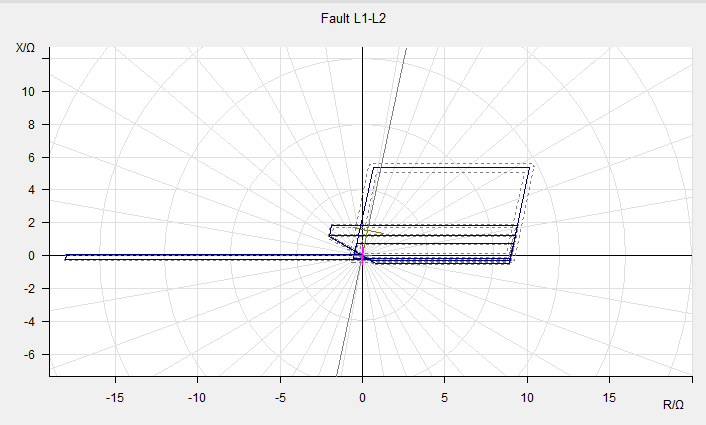
Figure 7: OMICRON Test Universe — Phase-to-Phase (Fault L1–L2) Loop
Technical Check: The right-hand resistive blinder stops at R ≈ 9.26 Ω, which accurately reflects the phase fault formula (Rph/2 = 18/2 = 9 Ω plus line tilt addition). Comparing Figure 6 and Figure 7 verifies that the test curves reflect genuine fault-loop physics rather than duplicate boxes.
Important Technical Points Observed in the Plotted Curves
-
Handling Extreme Aspect Ratios (Reverse Zone 4):
In this relay setting, Zone 4 reverse reach has a small reactance (Z4 = 0.25 Ω, vertical height around 0.245 Ω) combined with an 18.00 Ω resistive reach. This creates an extreme 73:1 aspect ratio—a flat strip extending from 0 to -18.00 Ω. Across all test software captures, this flat shape renders cleanly as a closed polygon without graphic distortion or software freezing.
-
Reverse Busbar Offset Wedge:
Behind the origin (0,0), inside Quadrants 2 and 3, a small triangular wedge is visible in Zone 3 / Zone P. This represents the relay’s 0.14 Ω reverse offset, provided for directional discrimination and security during close-in reverse busbar faults.
-
Correct Fault Loop Sizing:
Earth fault loops expand to 18 Ω, while phase fault loops terminate at 9.26 Ω. This confirms that the test curves reflect real fault-loop physics rather than generic copies.
Complete Secondary Injection Relay Test Kits with Ready Templates
For testing agencies, commissioning contractors, and state transmission utilities looking for dependable secondary injection test equipment:
-
Hardware Precision & Output Compliance: Tesient and CROXS 3-phase and 6-phase secondary injection kits provide high compliance voltage and stable current amplifiers designed for demanding transmission line distance and differential protection schemes.
-
Complimentary Templates for Kit Buyers: When you invest in a Tesient or CROXS test kit through Myriad Industrial Solutions LLP, all project-specific relay test templates and library files required for your substation relays are provided completely free of charge.
Professional Template Generation Services for Existing Test Sets
If your testing team already operates other test sets (such as Megger RTMS or OMICRON) and you are stuck on site because an exported setting file will not draw on your screen:
We provide Paid Ready-to-Test Template Services:
-
Send us your active relay setting file or setting sheet (MiCOM, Siemens SIPROTEC, ABB, GE, or SEL).
-
We compile, mathematically verify, and supply ready-to-test native template files configured for your specific test set software.
3. Save hours of manual coordinate entry on site and keep your commissioning schedule moving forward smoothly.
Disclaimer & Intellectual Property Notice
Disclaimer: All brand names, product models, and software trademarks referenced in this article (including OMICRON Test Universe, Megger RTMS / PowerDB, Schneider Electric / Alstom MiCOM, Siemens SIPROTEC, ABB / Hitachi Energy, and GE) are the registered property of their respective trademark holders. Reference to these brands is made solely for technical identification, compatibility analysis, and educational demonstration within power system protection engineering. Myriad Industrial Solutions LLP is an independent distributor and engineering solution provider and does not represent these third-party OEMs unless expressly stated. Relay setting values shown are from anonymized historical commissioning records used exclusively for mathematical validation.
Contact for Secondary Injection Test Kits & Template Support:
- Company: Myriad Industrial Solutions LLP, Mumbai
- Authorized Distributor: Tesient & CROXS Secondary Injection Relay Test Kits
- Technical Website: www.electricaltestkit.com
- Phone / WhatsApp: +91 8454940731
- Email: mail@electricaltestkit.com
- Office: Mumbai, Maharashtra, India
