


Secondary injection testing of numerical distance relays (ANSI 21/21N) across multi-vendor test sets often fails due to proprietary VBScript formulas and dynamic variable structures in OEM configuration files. Converting protection settings into statically evaluated XRIO impedance boundaries ensures 100% geometric parity, directional blinder accuracy, and operating times across OMICRON Test Universe, Tesient MPWin, Kingsine, and CROXS test software without vendor lock-in.
1. Transmission Feeder Benchmark & Relay Data
This cross-platform validation uses live setting parameters from an Alstom / Schneider MiCOM P442 numerical transmission distance relay installed on a 230 kV line:
- Relay Model: MiCOM P442
- Nominal System Frequency (fn): 50 Hz
- Phase CT Ratio: 1200 / 1 A (Ratio = 1200)
- Main VT Ratio: 230 kV / 110 V (Ratio = 2090.91)
- Line Positive Sequence Impedance (Z1 sec): 8.80 Ω ∠ 78.8°
- Secondary Line Resistance (RL): 1.71 Ω
- Secondary Line Reactance (XL): 8.63 Ω
- Line Replica Angle (ΦL): 78.8°
- Load Blinders: Disabled in active settings
2. Multi-Zone Parameter Setting Matrix
Modern numerical distance relays utilise polygonal quadrilateral characteristics to independently control reactive reach (X) and resistive boundaries (R). The evaluated secondary values and timers across all active stages are structured as follows:
| Protection Zone | Operating State | Direction | Reactive Reach (X) | Phase Resistance (RPh) | Ground Resistance (RG) | Trip Delay (t) | Earth Factor (kL ∠ θ°) | Line Reactance Coverage |
|---|---|---|---|---|---|---|---|---|
| Zone 1 | Active (ON) | Forward | 6.16 Ω | 6.0 Ω | 19.0 Ω | 0.00 s | 0.875 ∠ 1.2° | 71.4% of Line X |
| Zone 1X | Disabled (OFF) | Forward | 15.00 Ω | 6.0 Ω | 19.0 Ω | 0.00 s | 0.875 ∠ 1.2° | Extended / AR Stage |
| Zone 2 | Active (ON) | Forward | 8.86 Ω | 7.5 Ω | 23.75 Ω | 0.35 s | 0.875 ∠ 1.2° | 102.7% of Line X |
| Zone 3 | Active (ON) | Forward | 26.95 Ω | 10.0 Ω | 30.0 Ω | 0.80 s | 0.875 ∠ 1.2° | Remote Bus Backup |
| Zone 4 | Active (ON) | Reverse | 1.79 Ω | 10.0 Ω | 30.0 Ω | 10.00 s | 0.875 ∠ 1.2° | Long Reverse Backup |
| Zone P | Active (ON) | Reverse | 1.79 Ω | 3.0 Ω | 7.0 Ω | 0.30 s | 0.831 ∠ 0.4° | Carrier / DEF Blocking |
| Zone Q | Disabled (OFF) | Forward | 0.001 Ω | 0.03 Ω | 0.0 Ω | 0.50 s | 1.000 ∠ 0° | Inactive |
3. Engineering Analysis: Loop Blinder Shifts and Reverse Offset
A primary cause of cross-platform testing errors is the mishandling of loop-dependent resistive blinders. During phase-to-phase faults (L-L), the relay clamps the resistive reach tightly to RPh = 6.0 Ω, 7.5 Ω, and 10.0 Ω to prevent nuisance tripping during heavy power flow or system swings. During phase-to-ground faults (L-E), the resistive boundary expands by approximately 3.15 times to RG = 19.0 Ω, 23.75 Ω, and 30.0 Ω to ensure detection of high-resistance tower ground arcs.
In the third quadrant of the impedance plane, the relay establishes two independent reverse offset stages that share an identical reactive reach of X = 1.79 Ω. Zone P operates with a tight resistive blinder of RG = 7.0 Ω and a fast 300 ms timer for carrier-aided directional comparison blocking. In contrast, Zone 4 uses an expanded resistive envelope of RG = 30.0 Ω with a 10.0-second delay to provide long-time remote backup for uncleared reverse busbar faults.
4. Multi-Platform R-X Verification Proof
Compiling raw manufacturer settings into static, evaluated XRIO geometry eliminates calculation errors and delivers identical complex impedance planes across diverse secondary injection platforms:
OMICRON Test Universe (Advanced Distance)
Plots all three forward envelopes cleanly up to X = 26.95 Ω, demonstrating clear boundary expansion between L-E and L-L modes, while correctly anchoring reverse Zone 4 and Zone P in Quadrant 3.
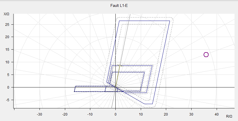 Figure 1: Phase-to-Earth (L1-E) Quadrilateral Characteristic on OMICRON Test Universe showing expanded RG resistive blinders and reverse Zone 4 / Zone P stages.
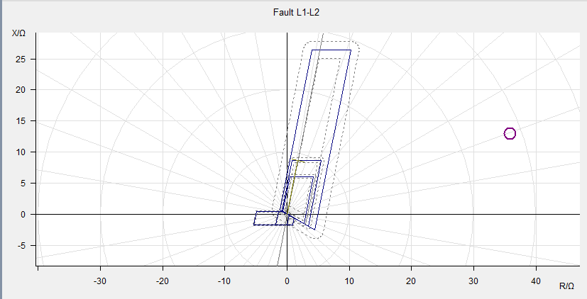 Figure 2: Phase-to-Phase (L1-L2) Quadrilateral Characteristic on OMICRON Test Universe displaying contracted RPh resistive blinder boundaries.
Tesient MPWin
Successfully renders the 78.8° line angle and complete 5-zone quadrilateral geometry without runtime VBScript parsing failures or missing boundary lines.
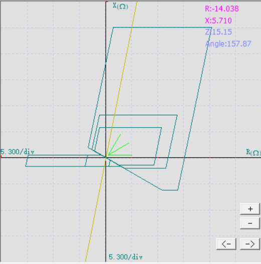 Figure 3: Phase-to-Earth (L-E) Quadrilateral Characteristic on Tesient MPWin confirming 5-zone reach and ground blinder parity from static XRIO.
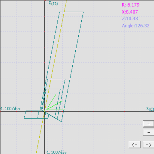 Figure 4: Phase-to-Phase (L-L) Quadrilateral Characteristic on Tesient MPWin validating phase blinder clamping without calculation faults.
Kingsine Relay Testing Suite
Confirms exact boundary parity across both phase-to-ground and phase-to-phase fault injections, correctly applying the resistive blinder expansion and tolerance bands.
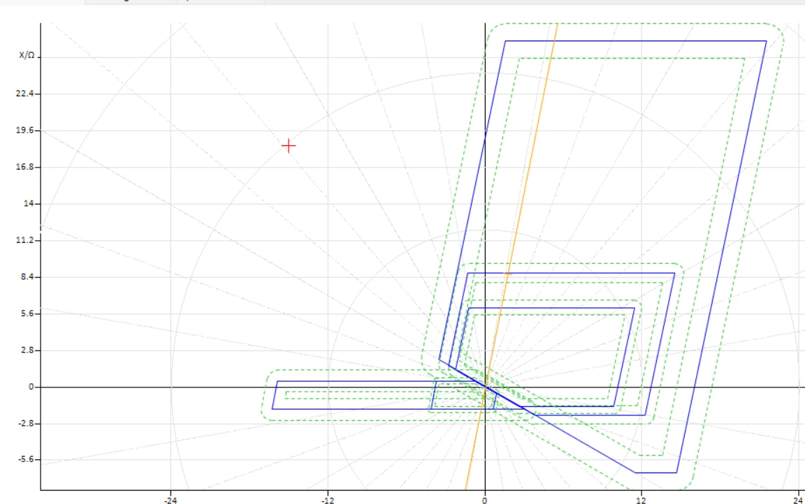 Figure 5: Phase-to-Earth (L-E) Quadrilateral Characteristic on Kingsine software showing outer reach envelopes and reverse stage offset.
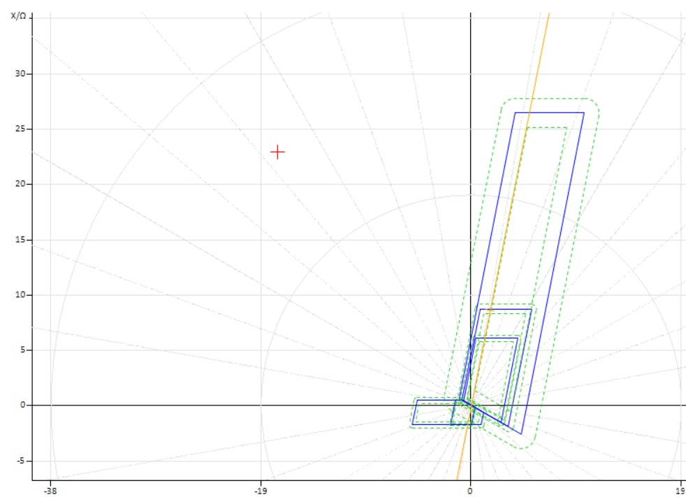 Figure 6: Phase-to-Phase (L-L) Quadrilateral Characteristic on Kingsine software demonstrating phase blinder narrowing and tolerance margins.
CROXS Testing Engine
Verifies multi-zone boundary continuity, labeling Zones 1, 2, 3, and reverse stages with precise coordinate alignment at the directional origin.
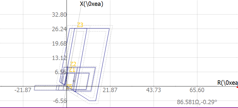 Figure 7: Multi-Zone Impedance Characteristic on CROXS engine verifying boundary continuity, directional origin, and Zone 1 to Zone 3 reach coordinates.
5. Standard Secondary Injection Procedure
- Hardware Isolation and Interfacing: Isolate breaker trip circuits, connect three-phase secondary currents (IA, IB, IC, IN) and voltages (VA, VB, VC, VN) to the relay test switch terminals, and wire the trip contacts into the test set binary inputs.
- Zone 1 Reach Verification: Inject along the line angle (78.8°) at 70% of Zone 1 reach (4.31 Ω) to confirm instantaneous operation under 30 ms. Inject at 105% of reach (6.47 Ω) to confirm transition into Zone 2 operating time (350 ms).
- Resistive Blinder Verification: Fix reactance at mid-reach (X = 3.08 Ω) and incrementally ramp resistance to verify that phase-to-phase tripping cuts off at 6.0 Ω, while phase-to-ground sensitivity extends out to 19.0 Ω.
- Reverse Stage Timing: Invert the fault current phase angle by 180° into Quadrant 3 to confirm Zone P trips at 300 ms for close-in reverse faults, while outer reverse reaches operate at the dedicated 10.0-second timer.
