


Frequency protection is one of the most important functions in modern electrical power systems because system frequency directly reflects the balance between generation and load.
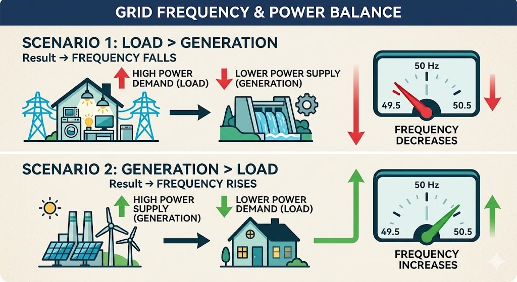
Whenever generation becomes lower than system demand, frequency falls. When generation exceeds demand, frequency rises. Severe deviations can damage generators, destabilise the grid, trigger cascading outages, or cause a complete system collapse.
Protection relays, therefore, continuously monitor system frequency and initiate corrective actions such as the following:
- Under frequency load shedding
- Generator tripping
- Turbine protection
- Islanding detection
- Process shutdown
- Grid separation
- System restoration logic
This article explains the practical principles of frequency protection testing, relay operating methods, dynamic frequency ramp testing, ROCOF verification, and important commissioning considerations.
What is Frequency Protection?
Frequency protection supervises the electrical system's frequency and operates when the measured frequency crosses predefined thresholds or changes too rapidly.
The most common ANSI functions are:
ANSI Function Description
81U: Under Frequency Protection
81O Over Frequency Protection
81R ROCOF (Rate of Change of Frequency) Protection
81UFLS Under Frequency Load Shedding
Under-frequency protection is typically used to:
- Prevent generator instability
- Avoid turbine damage
- Protect islanded systems
- Initiate automatic load shedding
- Prevent total grid collapse
Over-frequency protection is used to protect against:
- Generators
- Turbines
- Rotating equipment
- Captive power plants
- Small isolated grids
ROCOF protection is commonly used for:
- Anti-islanding schemes
- Renewable energy systems
- Distributed generation
- Fast disturbance detection
- Microgrid protection
Why Frequency Deviations Occur
Frequency changes whenever the active power balance is disturbed.
Frequency Drops When:
- Large loads are connected
- Generators trip
- Transmission lines disconnect
- Renewable output suddenly decreases
- System islands form unexpectedly
Frequency Rises When:
- Large industrial loads disconnect
- Excess generation remains online
- Islanding occurs with low load demand
- Turbine governing malfunctions occur
In large interconnected grids, frequency changes relatively slowly because of high system inertia.
In smaller systems such as:
- Diesel power plants
- Hydro stations
- Captive power systems
- Industrial microgrids
- Renewable hybrid systems
Frequency may change very rapidly.
- How Frequency Relays Measure Frequency
Modern numerical relays generally estimate frequency using the following:
- Phase-Locked Loop (PLL) algorithms
- Zero-crossing methods
- Fourier analysis
- Digital filtering techniques
- Sliding window calculations
Unlike voltage magnitude measurement, frequency measurement always requires observation over time.
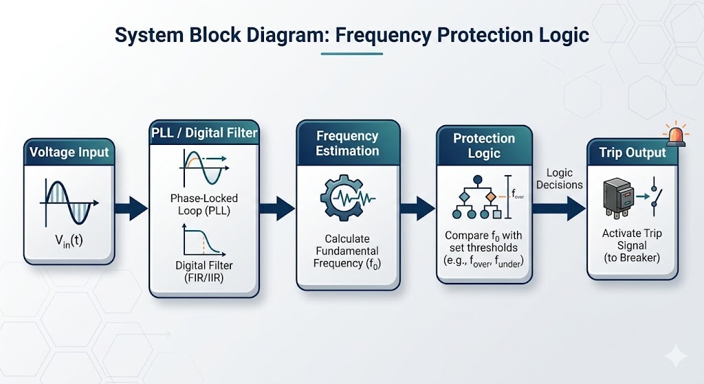
Therefore, frequency estimation inherently includes the following:
- Signal processing delay
- Filtering delay
- Decision latency
- Dynamic uncertainty during transients
This factor becomes critical during commissioning and relay timing interpretation.
Types of Frequency Protection Tests
Test Type Purpose
Pickup Test Verify operate threshold
Reset Test Verify reset value
Operate Time Test Verify trip delay.
Frequency Ramp Test Verify dynamic response
ROCOF Test Verify df/dt response
Multi-stage Test Verify UFLS coordination
Logic Test Verify breaker and interlock logic
Under Frequency Relay Testing (81U)
Under-frequency testing verifies that the relay operates correctly when system frequency falls configured thresholds
Example Settings
Stage Setting Delay
UF1 49.0 Hz 10 s
UF2 48.5 Hz 2 s
UF3 48.0 Hz 0.5 s
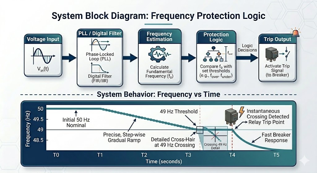
Typical Test Procedure
- Apply rated voltage and nominal frequency.
- Reduce frequency gradually or step directly below the setting.
- Measure pickup frequency.
- Measure operate time.
- Verify trip contact operation.
- Verify relay reset behaviour.
Over Frequency Relay Testing (81O)
Over-frequency protection testing is similar to under-frequency testing, but the injected frequency is increased above the nominal value.
Applications include:
- Generator overspeed protection
- Hydro turbine protection
- Gas turbine protection
- Islanded industrial power systems
- Renewable energy systems
Some relays use different filtering or timing logic for over-frequency elements. Therefore, both under-frequency and over-frequency functions should always be tested independently.
____________________________________________________________________________________________________________________
Static Frequency Injection vs Dynamic Frequency Testing
This is one of the most misunderstood areas in protection relay testing.
Static Frequency Injection
In static testing:
- Frequency is changed in discrete steps
- The relay stabilises at each value
- Pickup and timing are measured
Example:
- Inject 50 Hz
- Suddenly change to 48.8 Hz
- Measure trip response
Static testing is simple and useful for basic commissioning.
However, real power systems rarely change frequency instantaneously.
________________________________________________________________________________________________________________
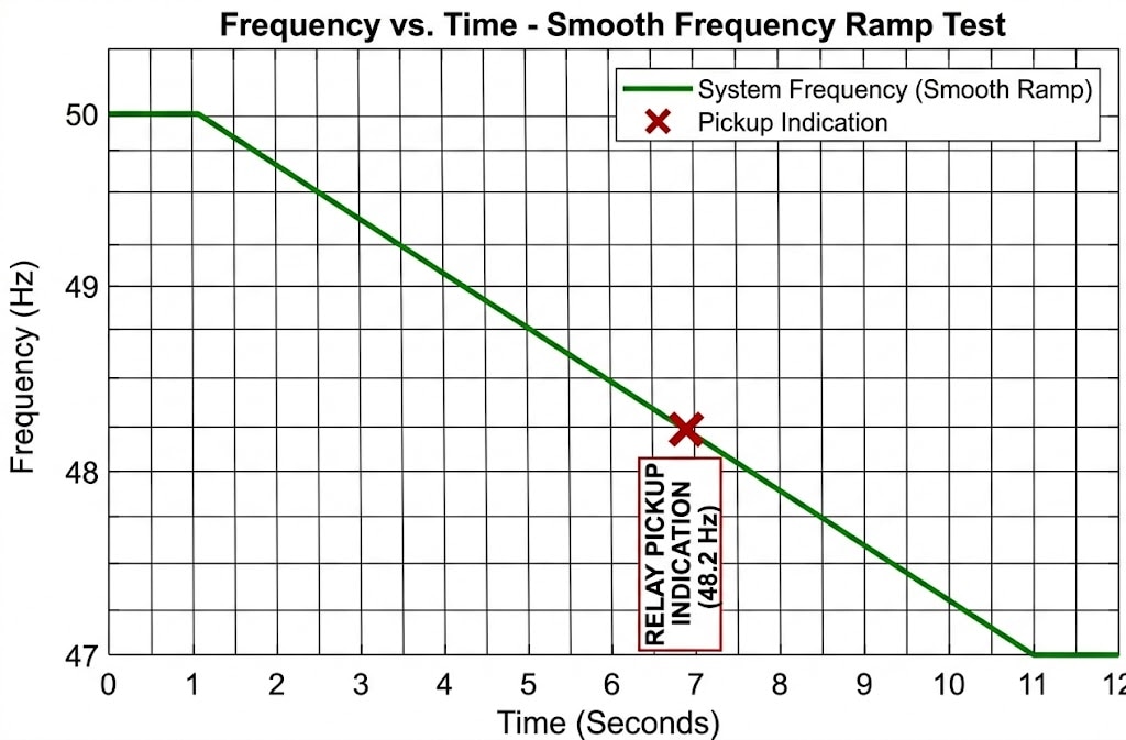
Dynamic Frequency Ramp Testing
Real system disturbances generally produce continuous frequency change rather than step transitions.
Dynamic testing therefore uses:
- Smooth frequency ramps
- Programmable profiles
- Disturbance playback files
- Controlled ROCOF profiles
Example:
Frequency decreases continuously from the following:
50 Hz → 49 Hz → 48 Hz
at a controlled ramp rate.
Dynamic testing is extremely important for:
- ROCOF protection
- UFLS schemes
- Renewable integration
- Microgrids
- Generator islanding protection
ROCOF Protection Testing
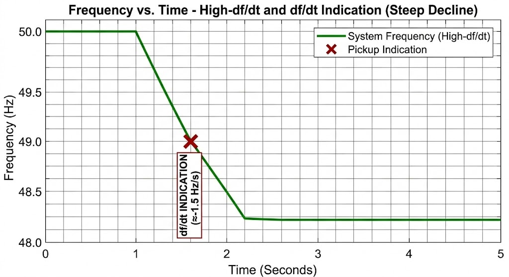
ROCOF protection measures the rate of change of frequency rather than the absolute frequency.
Typical settings include:
- 0.5 Hz/s
- 1 Hz/s
- 2 Hz/s
ROCOF protection allows faster detection of severe system instability.
However, ROCOF testing is technically demanding because:
- Relay algorithms differ significantly
- PLL implementations vary
- Filtering strongly affects operation
- Measurement windows differ
- Transient oscillations may cause false trips
A relay test set used for ROCOF testing should support:
- Smooth phase continuity
- Accurate frequency ramps
- Low waveform distortion
- Stable frequency synthesis
- Precise timing measurement
Important Practical Challenges in Frequency Testing
1. Relay Filtering Delay
Frequency relays never react instantaneously.
The relay requires:
- Measurement windows
- Digital filtering
- Signal stabilization
- Protection decision logic
Therefore:
- Internal relay timing
- External binary input timing
- Actual power system response time
are different physical quantities.
This distinction is critical during FAT and commissioning interpretation.
2. Ramp Rate Dependency
Relay operatingracteristics may vary depending on the following:amp speed
- Filtering settings
- PLL design
- Measurement window length
A relay tested at:
0.1 Hz/s
may behave differently from the same relay tested at:
2 Hz/s.
Therefore,frequency test reports should always mention the following:
- Ramp profile
- Starting frequency
- Ramp rate
- Timing methodology
3. Phase Discontinuity Problems
Poor signal generation may create the following:
- Phase jumps
- Waveform discontinuities
- PLL instability
- False ROCOF operation
Professional relay test systems maintain continuous waveform synthesis during frequency transitions.
4. Binary Input Timing Interpretation
External trip timing includes the following:
- Relay operate delay
- Output contact delay
- Binary input detection delay
- Test-set timing uncertainty
Therefore, externally measured trip time will naturally differ from internal relay algorithm timing.
How to Test Frequency Protection Using a Relay Test Set
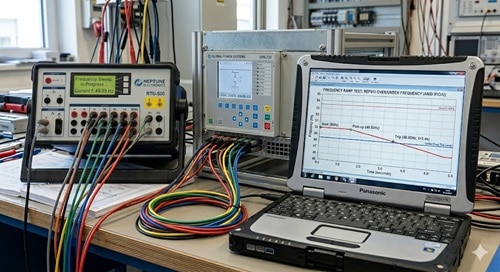
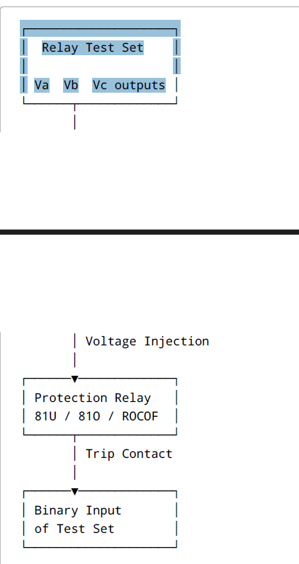
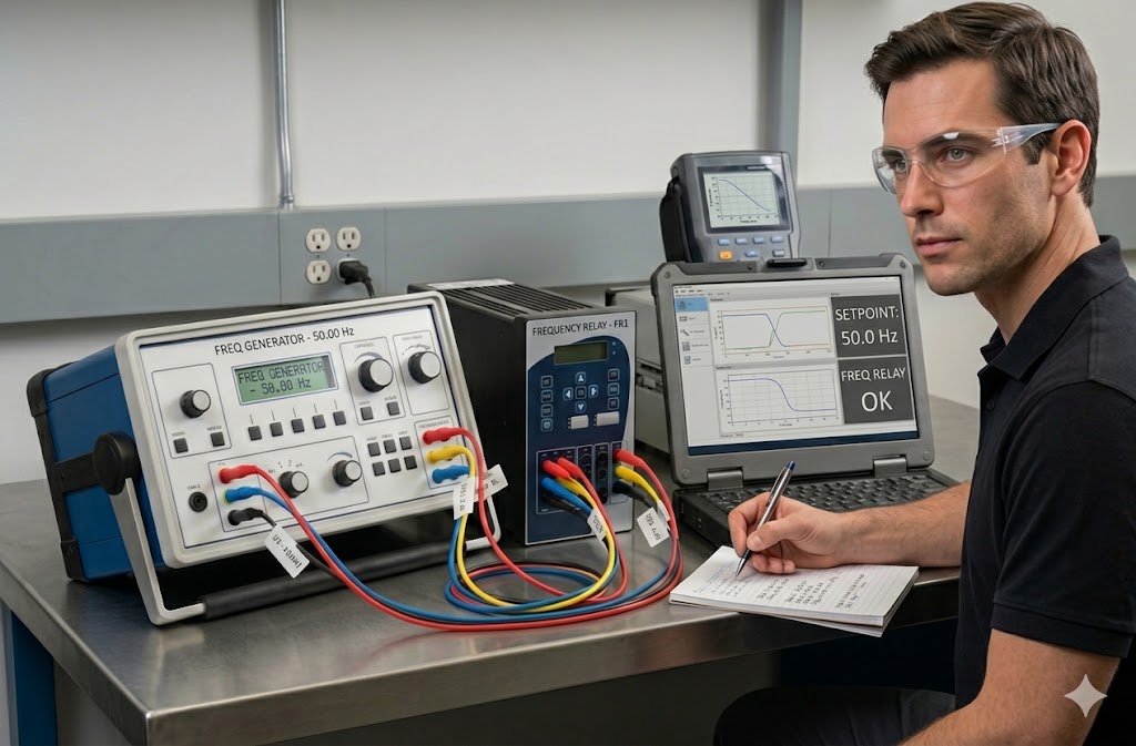
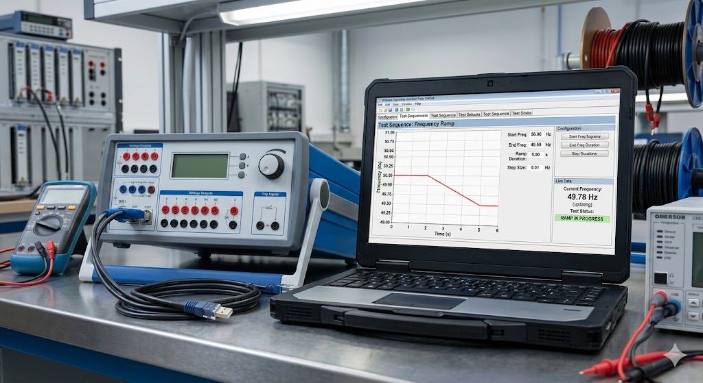
Frequency protection relays are normally tested using a secondary injection relay test kit. The relay test set generates stable AC voltage signals with controlled frequency variation, allowing the engineer to simulate real power-system frequency disturbances.
In most frequency protection tests, only voltage injection is required because frequency elements generally calculate frequency from voltage inputs.
___________________________________________________________________________________________________________________
Typical Test Setup
The relay test set voltage outputs are connected to the relay VT inputs.
The relay trip contact is connected back to the binary input of the relay test kit so that oper timing can be measured automatically.
Basic Connection Diagram
Step-by-Step Under Frequency Relay Testing
The following example explains practical testing of an 81U under-frequency relay.
Example Relay Setting
Parameter Value
Nominal Frequency 50 Hz
Under Frequency Pickup: 49.0 Hz
Intentional Delay 2 seconds
Step 1 – Apply Normal System Conditions
Inject normal voltage and frequency.
Example:
- 110 V AC
- 50 Hz
Verify:
- Relay remains healthy
- No trip occurs
- Frequency measurement is stable
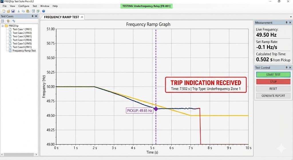
Step 2 – Configure Frequency Ramp
The relay test set software is configured to gradually reduce frequency.
Example Ramp
Parameter Value
Start Frequency 50 Hz
Stop Frequency 47 Hz
Ramp Rate 0.2 Hz/s
The relay test set now simulates a slowly collapsing power-system frequency.
Frequency Ramp Illustration
Frequency (Hz)
50 |
49 | \ ← Relay Pickup Setting
48 |
47 |
+---------------------- Time
Step 3 – Start Frequency Injection
When the test starts:
- Frequency gradually decreases
- A relay continuously measures system frequency
- Relay filtering and PLL algorithms process the waveform
- Relay output operates after pickup and delay conditions are satisfied
The relay test set measures:
- Pickup frequency
- Operate time
- Trip output status
Step 4 – Verify Pickup Frequency
Suppose:
- Relay setting = 49.0 Hz
- Measured pickup = 48.96 Hz
The measured value is compared against acceptable tolerance.
Minor deviation is normal because numerical relays use the following:
- filtering,
- averaging,
- and digital frequency estimation.
Step 5 – Verify Operate Time
After frequency crosses the pickup threshold, the relay's intentional delay timer starts.
The total measured operating time includes the following:
- Relay filtering delay
- Intentional time delay
- Output contact operation time
- Binary input response time
Therefore, external operating timing will always be slightly larger than internal relay algorithm timing.
Timing Illustration
Frequency crosses 49 Hz
│
▼
──────────────────────────────
The rel etects the picku
│
▼
Intentional delay runs
│
▼
Relay trips
│
▼
Binary input detects output
Testing Over-Frequency Protection (81O)
Over-frequency testing is similar to under-frequency testing except that frequency is increased above the nominal value.
Example:
- Start at 50 Hz
- Increase towards 52 Hz
- Verify pickup and timing
Applications include:
- Generator overspeed protection
- Turbine protection
- Islanded power systems
Testing ROCOF Protection
ROCOF protection measures how quickly frequency changes.
Instead of absolute frequency, the relay measures the following:
Rate of frequency change (Hz/s).
Example:
- ROCOF setting = 1 Hz/s
The relay test set must generate smooth continuous frequency ramps without phase jumps.
Poor waveform generation may create:
- false trips,
- unstable measurement,
- or incorrect ROCOF operation.
ROCOF Ramp Illustration
Frequency
50 |
49 |
48 |
47 |
+---------------- Time
Steeper slope = Higher ROCOF
Important Practical Points
Frequency relays never respond instantly.
Frequency measurement requires the following:
- waveform observation,
- digital filtering,
- and signal processing.
Therefore, some operating delay always exists.
Ramp Rate Matters
A relay tested at:
- 0.1 Hz/s
may operate differently from the same relay tested at
- 2 Hz/s.
Therefore, test reports should always mention the following:
- ramp rate,
- starting frequency,
- stopping frequency,
- and timing methodology.
Phase Continuity is important.
High-quality relay test sets maintain smooth waveform continuity during frequency transition.
Sudden phase discontinuity may:
- disturb PLL operation,
- create false ROCOF response,
- or produce incorrect timing.
Relay Test Set Requirements for Frequency Testing
A professional relay test set used for frequency protection testing should support:
Requirement Importance
Smooth Frequency Ramping Prevent false operation
Phase Continuity Essential for ROCOF testing
Low Distortion Outputs Stable relay measurement
Accurate Timing Reliable trip analysis
Programmable Profiles Realistic disturbance simulation
Automation Capability Multi-stage UFLS verification
Under Frequency Load Shedding (UFLS) Testing
UFLS schemes usually contain:
- Multiple frequency stages
- Intentional delays
- Breaker coordination logic
- Restoration interlocks
- Priority-based feeder shedding
Testing should verify:
- Correct stage operation
- Breaker coordination
- Restoration sequence
- Logic selectivity
- Total scheme response time
Testing only the individual relay element is often insufficient.
Complete scheme-level dynamic verification is recommended.
Generator and Islanding Applications
Frequency protection is critically important in the following:
- Diesel generator systems
- Hydro power stations
- Gas turbines
- Renewable plants
- Industrial captive power systems
- Microgrids
Small isolated systems generally have:
- Lower inertia
- Faster frequency collapse
- Higher ROCOF values
- Greater dynamic instability
Therefore, frequency settings that work correctly in large utility grids may become unstable in smaller islanded systems.
Testing should reflect realistic site operating conditions as closely as possible.
Common Mistakes During Frequency Protection Testing
Using Unrealistic Ramp Rates
Very fast ramps may create non-physical results.
Ignoring Relay Filtering
Different relay manufacturers use different filtering techniques.
Confusing Internal and External Timing
These are different physical measurements.
Using Unstable Signal Sources
Poor waveform quality may distort results.
Testing Only Pickup Values
Complete dynamic verification is often ignored.
Ignoring Scheme Coordination
UFLS systems require complete logic verification.
Conclusion
Frequency protection testing is far more complex than simply changing the injected frequency and observing a trip output.
Accurate verification requires understanding:
- Relay algorithms
- Dynamic frequency behavior
- PLL operation
- Timing interpretation
- Ramp generation quality
- Binary input timing
System inertia effects
As modern power systems increasingly depend on the following:
- Renewable energy
- Distributed generation
- Microgrids
- Automated load shedding
- Grid stability schemes
Proper frequency protection testing becomes increasingly important for system reliability and operational security.
Engineers should therefore evaluate not only whether the relay trips, but also the following:
- How the frequency waveform is generated
- How ramps are applied
- How timing is interpreted
- Whether the test realistically represents actual system disturbances
