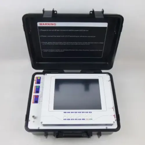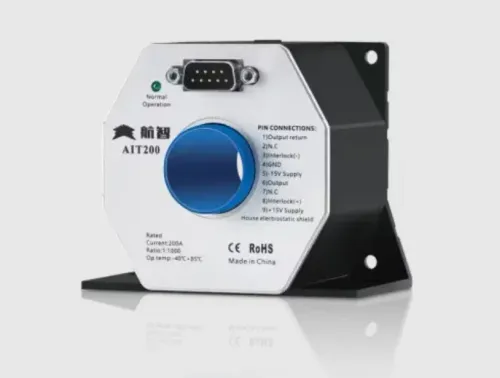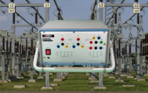


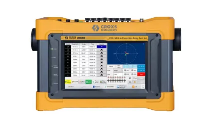
A relay test system is only “high accuracy” when its errors, operating conditions and timing path are documented well enough to compare with the relay’s test tolerances. By the end, you will be able to match the CROXS system’s specifications, channels, interfaces and software workflow to the protection functions and field tasks you actually perform.
Key takeaways
- Check guaranteed error, uncertainty and test conditions—not one headline accuracy percentage.
- Match output channels and software functions to your relay schemes and test plans.
- Confirm the complete workflow, including wiring, timing, fault simulation and report generation.
- Choose CROXS when repeatable advanced protection testing outweighs setup and training effort.
What does high accuracy mean in relay testing?
“High accuracy” is not a standard equipment class. The phrase “croxs advanced protection relay test system high accuracy for engineers” proves nothing until you see guaranteed errors, measurement uncertainty and test conditions. A single percentage headline cannot establish whether the system is suitable for protection work.
| Evidence to examine | Why it matters |
|---|---|
| Voltage and current magnitude error, resolution and stated accuracy class | Establishes whether pickup and operating quantities are credible |
| Phase-angle error and frequency accuracy | Matters to directional, distance, differential and df/dt elements |
| Timer accuracy and binary-input timing | Separates source, relay, contact or communications delay from the test-set result |
| Operating range, burden, temperature and simultaneous-channel limits | Shows whether accuracy holds near minimum output and under real loading |
| Transient capability, compliance voltage and waveform playback | Determines whether CT saturation, DC offset, harmonics and differential stability can be reproduced |
Timing evidence must identify separate performance for dry contacts, wet contacts, logic inputs and IEC 61850 messages. Ask how input debounce, output-contact latency and the timer reference enter the reported trip time.
For high accuracy relay testing equipment, request calibration data and uncertainty budgets at the actual test points, not only a certificate at nominal conditions. If you need Sampled Values or GOOSE, verify sampling rate, synchronisation, message profiles, quality flags and lost-message behaviour; analog accuracy alone does not prove process-bus coverage.
Which relays and protection schemes can it test?
Match the test set to the relay’s sensing method and the fault it must reproduce. A CROXS Advanced Protection Relay Test System high accuracy specification does not by itself prove suitability for every scheme: confirm the required current and voltage channels, output burden, compliance voltage, waveform playback and binary inputs.
| Relay or scheme | Test-system match | Capability to verify |
|---|---|---|
| Electromechanical overcurrent or earth-fault relay | Steady-state current injection with accurate timing and adjustable pickup values | Current output, burden capacity, contact-input timing and safe trip capture |
| Static or numerical overcurrent, underfrequency or df/dt relay | Independent current, voltage and frequency channels with programmable ramps and sequences | Channel count, frequency resolution, ramp control and binary-input timing |
| Distance protection | Three-phase voltage and current outputs with independent phase-angle control | Voltage-current phase accuracy, simultaneous-channel performance and power capability |
| Differential protection | Matched multi-channel injection for operating and restraint quantities | Current-channel independence, amplitude and phase control, compliance voltage and saturation-test support |
| IEC 61850-enabled relay | Analog outputs plus a digital protocol test function | GOOSE, Sampled Values, datasets, quality flags, time synchronisation and event recording |
Do not assume analog channels test an IEC 61850 scheme, or that sine-wave accuracy reproduces CT saturation. For differential and transformer protection, ask whether the system supports recorded-waveform playback, DC offset, harmonics and remanence.
Also check that the output count covers every simultaneous phase, neutral and restraint quantity; adding channels after purchase may require a different hardware configuration.
What does a complete test workflow look like?
A complete workflow can take you from wiring and configuration to automated results and a formal report, provided the test set supports every required signal path and protocol.
1. Connect the relay’s current and voltage circuits to the output channels, then wire trip contacts to binary inputs. Confirm polarity, channel mapping, grounding and safe output limits before energising anything.
2. Select the relay model, protection function and nominal settings. Enter pickup values, time curves, tolerances and test points so the software can judge pass or fail instead of merely recording measurements.
3. Build the test sequence for overcurrent, earth-fault, distance or differential elements. Include pre-fault conditions, ramp or pulse injections, fault quantities and reset intervals.
4. Inject the programmed quantities and capture pickup, operate time, trip contact state and reset behaviour. The timer result must identify its reference and account for relay, contact, input and communications latency.
5. For IEC 61850 work, verify separate support for GOOSE subscription and publication, Sampled Values, configurable datasets, quality flags, time synchronisation and packet-event recording. Analog outputs alone do not prove process-bus coverage.
6. Run the sequence automatically, pause for inspection when a result fails, and repeat selected points without rebuilding the test.
7. Review measured values against tolerances, attach notes and export a report containing settings, wiring or channel assignments, injections, trip times, pass/fail outcomes and event records. That audit trail is what turns advanced protection relay testing into defensible commissioning or maintenance evidence.
Which relay-engineer tasks justify the system?
The system earns its place when you need repeatable secondary-injection tests, controlled fault quantities, captured trip timing and a defensible report—not merely a convenient source of current and voltage. The CROXS relay test system for protection engineers is a practical fit when its output accuracy, timing path, channel capacity and safety controls match the test.
| Task | Practical fit | Check before committing |
|---|---|---|
| Commissioning | Verify pickup, dropout, operating time, phase response and logic for overcurrent, earth-fault, distance or differential relays after wiring | Confirm current and voltage channels, binary-input timing, output isolation and the required burden |
| Maintenance | Repeat baseline tests and compare relay settings, measured trip time and contact behaviour during scheduled outages | Check accuracy near low output levels and under simultaneous channel loading |
| Troubleshooting | Reproduce a recorded fault, vary one quantity at a time and identify whether the relay, wiring, logic or trip circuit caused the failure | Confirm dry-contact, wet-contact and communications timing specifications |
| Laboratory work | Build repeatable tests for numerical, static and electromechanical relays, including IEC 61850 Sampled Values where supported | Verify sampling rate, synchronization, message profiles and invalid-quality behaviour |
| End-to-end preparation | Coordinate source injection, relay operation, breaker-trip simulation and report capture before a field outage | Establish whether GPS, IRIG-B or PTP is needed; internal channel coherence is not absolute time synchronization |
Myriad Industrial Solutions LLP can add value by helping you match the CROXS configuration to the relay scheme rather than selecting a test set from its headline accuracy alone. Reject the setup if grounding, interlocks, emergency shutdown, thermal limits or backfeed protection do not fit your site procedure.
Related product
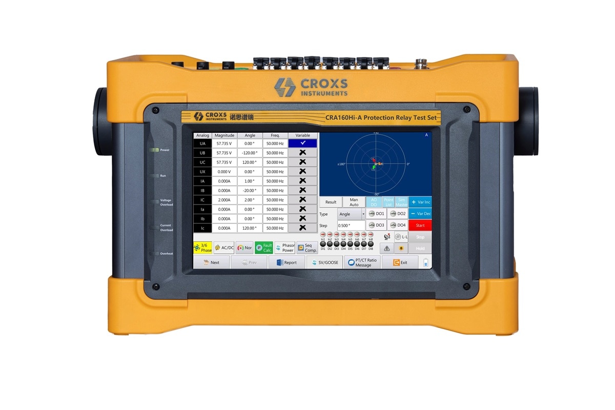 | Protection Relay Test System CROXS Advanced Protection Relay Test System (High Accuracy) Myriad Industrial Solutions LLP offers professional-grade protection relay test systems engineered for electrical substation commissioning,... View product → |
What should you verify before choosing the CROXS system?
Treat the purchase as unproven until the CROXS Advanced Protection Relay Test System’s high accuracy is supported by traceable documents and a witnessed test. Request separate guaranteed errors for voltage magnitude, current magnitude, phase angle, frequency, time and binary-input timing, plus measurement uncertainty and resolution.
Check the stated output range, load, temperature, frequency and simultaneous-channel conditions; accuracy can degrade at low output or high burden.
| Evidence | Ask for | Decision test |
|---|---|---|
| Accuracy certificate | Calibration traceability, stated errors and test conditions | Compare uncertainty with the relay manufacturer’s tolerance |
| Timing demonstration | Dry-contact, wet-contact, logic-input and IEC 61850 results | Include source, relay, debounce and timer-reference delay |
| Waveform demonstration | Playback, DC offset, harmonics, remanence, current and compliance-voltage limits | Do not infer CT-saturation or differential performance from sine waves |
| Safety file | Isolation, grounding, interlock, emergency stop, thermal limits and anti-backfeed design | Reject any mismatch with your switching procedure |
Before a site demonstration, verify:
- Output isolation and permitted grounding arrangements.
- Emergency shutdown and interlock operation under an active injection.
- Thermal limits at maximum current and with several channels operating.
- Secondary-terminal voltage, exposed-conductor controls and accidental-backfeed protection.
For high accuracy relay testing equipment, require a saved report showing pickup, trip time and channel conditions. For distance and differential tests, compare phase-angle error with the relay test tolerance; a small error near a characteristic boundary can change the result.
Frequently asked questions
What does high accuracy mean in relay testing?
High accuracy means documented guaranteed errors and measurement uncertainty under stated test conditions, not a single percentage claim. Check the ranges, loading, temperature and test functions covered.
Which relays and protection schemes can the CROXS system test?
Confirm the system’s output channels, current and voltage ranges, timing capability, binary inputs and software support against your specific relay types and schemes, such as overcurrent, distance, differential or transformer protection.
What does a complete test workflow look like?
A complete workflow covers test-plan selection, safe isolation, wiring, signal injection, relay-operation and timing measurements, result review, repeat testing and a documented report.
Which relay-engineer tasks justify the system?
The system is most valuable when you perform repeatable commissioning, maintenance, fault diagnosis, calibration or complex protection-scheme testing that demands controlled injections and traceable results.
What should you verify before choosing the CROXS system?
Verify accuracy specifications, uncertainty data, output capacity, supported relay protocols, software test modules, reporting, portability, safety features, calibration records and local technical support.