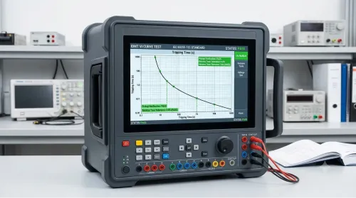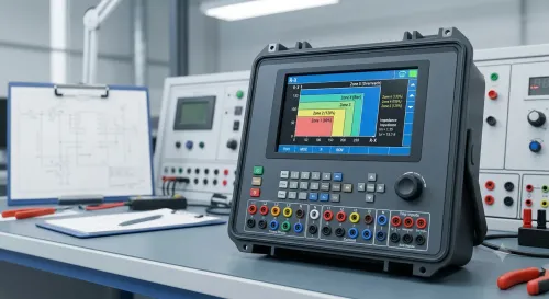



A digital relay test can fail because of the relay, the test set, the network, the time source or the laboratory’s configuration record. By tracing each part of the measurement chain and comparing three controlled test modes, you can identify the fault and judge whether a laboratory’s result is technically defensible.
Key takeaways
- Check reference output, Sampled Values, GOOSE, timing and trip output separately.
- Trace the full fault path before blaming the relay.
- Compare SCL files, VLAN tags and GOOSE datasets with the live configuration.
- Demand time-synchronisation records, repeat tests and raw digital evidence.
What an IEC 61850 relay test set actually measures
It measures more than a relay’s pickup and trip time. IEC 61850 calibration testing must account for the test-set reference, Sampled Values, GOOSE messages, Ethernet path, time source, relay input processing and binary trip output. A single failed trip points to relay logic only after these quantities agree and repeat.
| Symptom | What the test set reveals | More likely laboratory problem |
|---|---|---|
| Missed or delayed GOOSE trip | Packet receipt, APPID, dataset, latency and binary output timing | Wrong SCL mapping, VLAN, MAC address or switch configuration |
| Incorrect pickup with correct analogue output | Sampled-Value scaling, channel order and RMS or phase values at the relay | Merging-unit ratio, quality flag or subscription error |
| Drifting timestamps or unstable latency | PTP or other time synchronisation, packet timing and capture timestamps | Grandmaster, network congestion or interface configuration |
| Different result on repeated runs | Reference amplitude, frequency, phase, packet sequence and relay response | Software state, duplicated identifiers, stale datasets or wiring |
| Correct relay indication but wrong recorded trip time | Relay event timestamp compared with test-set and binary timestamps | Time-source or clock-domain error |
A conventional certificate for voltage, current, frequency, phase angle and analogue timing does not validate digital performance by itself. The laboratory must state whether it measured the complete chain, including network timing, packet processing and relay response; otherwise the certificate cannot support the claimed digital result.
A factory self-test proves equipment health, not project conformity. Check for:
- Required Sampled-Value profile and scaling
- GOOSE publish/subscribe diagnostics
- VLAN ID, priority, APPID and MAC settings
- Captured packets, timestamps and repeatability evidence
A NABL logo alone proves nothing about this service; inspect the exact accreditation scope.
Follow the fault path from reference output to relay trip
Check the chain in this order: test-set reference, merging unit, Ethernet path, time source, relay settings, then binary wiring. Moving downstream prevents a bad source or packet stream from being misdiagnosed as a relay defect.
1. Verify the relay test set’s analogue amplitude, frequency, phase angle and sampled-value scaling against its reference. A factory self-test proves equipment health, not the required IEC 61850 profile or dataset.
2. Check the merging unit’s channel mapping, nominal values and analogue-to-digital conversion. Incorrect CT or VT ratios produce wrong pickup values even when packets arrive correctly.
3. Inspect every Ethernet hop. Confirm VLAN ID, priority tag, APPID, MAC addresses, publisher/subscriber mapping, switch port configuration and packet captures. Many relay test set laboratory faults are Ethernet configuration faults, including duplicated identifiers and blocked GOOSE traffic.
4. Verify the time source at the relay input, not only at the test set. Record the PTP profile, grandmaster state, offset, loss-of-sync response and timestamp error; GPS lock alone proves nothing about synchronized Sampled Values.
5. Load the intended SCD, CID or ICD-derived configuration and confirm the relay setting revision, enabled elements, pickup values, logic equations and GOOSE dataset. A stale dataset can create a clean communication trace with no trip.
6. Prove binary wiring last. Check terminal identity, contact logic, polarity, wetting voltage, debounce time and input assignment. A valid relay decision still produces a missing trip if the output contact reaches the wrong input.
Capture evidence at each checkpoint, rather than relying on trip time alone. That isolates the first failed link in the chain.
Separate a relay defect from an SCL, VLAN or GOOSE configuration error
Run three controlled tests that change one layer at a time. This separates measurement accuracy from digital communication and, finally, the relay’s protection logic.
1. Prove the reference path. Apply known voltage, current, phase angle and frequency values, or known Sampled Values, and compare the result with an independent calibrated capture instrument. Keep the Ethernet path and relay settings fixed.
An amplitude, phase or timing error that appears before the relay receives the signal points to the test set, merging unit or measurement chain—not the relay logic.
2. Prove message behavior separately from operating time. Confirm the SCL dataset, publisher and subscriber, MAC address, AppID, VLAN ID, priority tag, quality bits, sample rate, PTP status and GOOSE retransmission sequence. Then introduce a wrong VLAN tag, missing synchronization, delayed GOOSE or dropped packets and check whether the procedure detects each fault.
A packet capture proves that a frame exists; it does not prove that the relay tripped within the required time.
3. Prove protection logic with known-good inputs. Send correctly scaled, synchronized Sampled Values and valid GOOSE messages through the verified network, then apply a fault that exceeds the relay pickup setting. A correct trip time confirms the logic path; no trip, incorrect pickup or wrong block response points to relay settings, firmware or internal logic.
This isolation prevents nabl relay testing problems from being mislabelled as relay defects. Repeatability alone does not establish traceability; retain the reference readings, packet evidence and timing results.
Define the calibration evidence a digital result needs
A digital relay result is defensible only when the laboratory defines the complete measurement chain, not just the analogue injection value. IEC 61850 calibration testing must identify the reference for amplitude, phase, frequency, Sampled Values scaling, packet timing, GOOSE state changes, trip delay and timestamp accuracy.
| Reference quantity | Uncertainty contribution to control | Evidence to retain |
|---|---|---|
| Amplitude, phase and frequency | Source accuracy, DAC/ADC error, merging-unit ratio and scaling | Traceable calibration certificates, range, uncertainty and test conditions |
| Sampled Values and GOOSE timing | PTP clock error, switch delay, jitter, packet loss and capture-clock error | Packet captures, PTP state, topology, VLAN, priority and AppID records |
| Relay response and trip time | Relay threshold, binary-output delay, wiring and analysis-software resolution | Settings revision, test sequence, pass/fail limits and raw timestamps |
The uncertainty budget must include every link from test-set output through Ethernet, switch, merging unit or relay input, capture instrument and analysis software. A conventional certificate for analogue output cannot support a digital relay claim that excludes packet processing and synchronisation.
Ask for the laboratory’s location-specific NABL accreditation scope. It must name the relevant quantities, ranges, uncertainty, method, environmental conditions and, where claimed, IEC 61850 or digital-protection testing. ISO/IEC 17025 accreditation alone does not cover every service at the site.
NABL relay testing problems appear when a report shows only injected values and trip times. Repeatability proves setup stability; traceability requires linked references, uncertainty calculations, equipment records, personnel competence and retained digital evidence.
Make digital relay results reproducible before choosing a laboratory
A defensible report preserves the complete digital chain, not just injected values and trip times. Include Sampled Values and GOOSE captures, packet timestamps, PTP state, network topology, relay setting revision, test-set firmware, test sequence, pass/fail limits and environmental conditions. Without those records, you cannot distinguish a relay fault from a VLAN, SCL or timing error.
Ask the laboratory for these items before placing the job:
- The stated Mumbai address, equipment identification, operator competency records and environmental-control records.
- Raw packet files, configuration files, event logs and analysis software version, with retention and export procedures.
- NABL scope details naming the IEC 61850 method, electrical quantities, range, uncertainty and environmental conditions.
- A measurement model covering the test-set output, Ethernet path, switch, merging unit or relay input, time source, capture instrument and software.
- A repeat test on your sample, with changed settings documented and the same evidence supplied.
| Check | Acceptable evidence | Reject or query |
|---|---|---|
| Equipment | SV profile, GOOSE dataset, timing and packet diagnostics demonstrated | Factory self-test only |
| Raw results | PCAP files, timestamps, PTP state and sequence record | Spreadsheet of values and trip times |
| Accreditation | Exact NABL scope covers the performed method and range | ISO/IEC 17025 logo without matching scope |
| Support | Supplier can reproduce exports and diagnose configurations | Firmware or software support is undocumented |
For buyers comparing digital relay test results in mumbai, location alone proves nothing. Myriad Industrial Solutions LLP becomes worth evaluating when its support team can run this evidence-led acceptance test and explain limitations; that is how you expose iec 61850 relay test set calibration laboratory problems in mumbai before the certificate is issued.
Related products
 | Protection Relay Test System CRA160Hi-A Three Phase Automatic Relay Test Set (IEC 61850 Digital Smart Grid Tester) The CROXS CRA160Hi-A is an automatic, secondary injection relay test system designed for digital substations, generation plants, and high-voltage... View product → |
 | Protection Relay Test System IEC 61850 Relay Test Set – MP3000F IEC 61850 Relay Test Set – Six-Phase, All-in-One Relay Test System (MP3000F) – Price & Supplier in India Need one relay test set that can test both... View product → |
Frequently asked questions
What does an IEC 61850 relay test set actually measure?
It measures the complete digital protection test chain: reference outputs, Sampled Values, GOOSE messages, Ethernet transport, time source, relay processing and binary trip output.
How can you separate a relay defect from an SCL, VLAN or GOOSE error?
Compare the configured SCL files, VLAN identifiers, GOOSE control blocks, datasets, message counters and received signals with the live relay and network configuration.
What calibration evidence should a digital relay result include?
Request the test-set reference data, Sampled Values and GOOSE records, time-synchronisation details, test settings, relay configuration, trip timestamps and repeat-test results.
How do you make digital relay results reproducible before choosing a laboratory?
Require a documented fault path, controlled network settings, traceable references, recorded time sources, saved configuration files and repeated tests that produce consistent results.
Related product
 | Protection Relay Test System CRA160Si-A Three Phase Automatic 6U6I Relay Test Set (IEC 61850 Digital Smart Grid Testing Kit) The CROXS CRA160Si-A is an automatic 6U6I secondary injection test system designed for digital substations, generation plants, and transmission... View product → |