

A credible current-transducer result starts before the first reading: you must define the device under test, choose a suitable reference and source, control the wiring and thermal conditions, and record enough data to reproduce the calculation. By the end, you will be able to build a test sequence, judge whether a 10 ppm claim applies to the complete measurement chain, and issue a result that distinguishes offset, gain, linearity, hysteresis, and uncertainty.
Key takeaways
- Match the reference path to ratio, offset, linearity, phase, or overload testing.
- Use guarded wiring and a defined burden to prevent setup errors.
- Treat 10 ppm as a complete system result, not a transducer-only claim.
- Document readings, conditions, calculations, and equipment decisions together.
Define the test objective and choose the correct reference path
The precision for current transducer testing process comes from matching the test objective to the complete measurement path. Decide whether you need ratio, offset, linearity, hysteresis, phase, or overload data, then identify the device type, standard, frequency range, burden, and environmental conditions before choosing instruments.
| Reference path | What it measures | When it applies |
|---|---|---|
| Precision shunt | Voltage proportional to primary current | DC or AC tests where the shunt’s power, bandwidth, and thermal limits are acceptable |
| Reference transducer | Current ratio, phase, and waveform response | High-current tests or when isolation and a defined reference output are required |
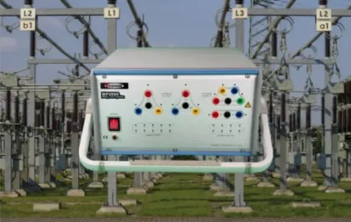
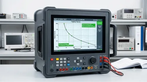
| CT analyser or calibrator | Instrument-transformer performance | CT testing, not automatically a substitute for a fluxgate transducer test |
Use a stable current source with enough compliance voltage for the primary circuit and enough capacity for the DUT and reference. For AC testing, record frequency, waveform, burden, and phase; a 50 Hz result does not establish performance at 60 Hz or at another frequency.
A distorted source can hide frequency-dependent error inside one RMS value.
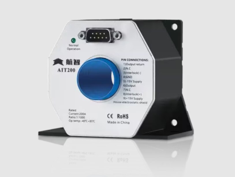
- Test a fluxgate transducer as a closed-loop device: include its specified supply, compensation winding, output polarity, and burden or load.
- Synchronise reference and DUT sampling. Different bandwidths, anti-alias filters, or trigger delays can create apparent phase error.
- Select a shunt, reference transducer, or CT analyser according to the device and claim being tested; do not apply IEC 61869 automatically to every electronic transducer.
- Specify the conductor position, warm-up time or stability limit, zero procedure, and thermal conditions before applying precision current.
Wire a fluxgate transducer without creating a measurement error
An off-centre primary conductor can create apparent offset or gain error before the DUT is energised. Treat the magnetic path, electrical load, and grounding as one measurement circuit.
1. Pass the primary conductor through the specified aperture in the marked direction, with one defined pass unless the manufacturer specifies turns. Centre it mechanically, keep bends away from the aperture, and route the return conductor away from the core. Remove nearby ferromagnetic brackets, tools, and current-carrying cables from the magnetic path.
2. Connect the manufacturer-specified DC supply to the DUT supply terminals with correct polarity and voltage. Use a stable, current-limited source, verify the wiring with power off, and connect protective earth where the equipment requires it.
3. Wire the compensation output to the specified burden or receiving instrument. Confirm whether the output is current or voltage, use the stated burden resistance and power rating, and check output polarity. An incorrect burden can force loop-compliance failure; an incorrect polarity can make the compensation winding reinforce, rather than oppose, primary flux.
4. Use twisted, shielded output leads and keep them separated from the primary and supply wiring. Terminate the shield exactly as the manufacturer specifies, normally at one defined end; never use the shield as the signal or protective-earth conductor.
5. Bond the DUT, reference instrument, source, and protective earth at the planned single grounding point. Avoid parallel earth paths that form loops, then connect the reference and DUT output channels to the same synchronised acquisition system.
This fluxgate current transducer setup must remain physically undisturbed during warm-up. Record the supply, burden, conductor orientation, grounding arrangement, and ambient temperature before energising.
Stabilise the system and run a complete current test matrix
Allow the DUT, reference, source, and primary conductor to reach thermal equilibrium before collecting precision readings. Use the specified supply voltage and output burden, and keep conductor position, shielding, grounding, frequency, and waveform unchanged. Apply the manufacturer’s warm-up time, or wait until successive zero readings meet a documented stability criterion.
Run the current matrix in a defined sequence:
- Record zero current before energising the primary, then record it again after the final sweep.
- Apply increasing current through low-range, mid-range, and full-scale points on the positive side.
- Return to zero, then repeat the same points with negative current.
- Add the manufacturer-permitted overload point only for the specified duration; never use overload to compensate for an incorrect range.
- Decrease current through the negative and positive points to capture the return path.
- Repeat the complete sweep enough times to quantify repeatability, using identical settling times at every point.
Record the reference and DUT outputs simultaneously at each settled point. For AC testing, log frequency, waveform, RMS or peak convention, burden, and phase condition; a 50 Hz result does not establish performance at another frequency. Keep the current source stable during each reading and note any drift.
A zero reading measures offset and drift, not ratio accuracy or saturation. Compare the initial and final zeros, and retain the sign convention in the data system. If positive and negative results disagree unexpectedly, stop and check polarity, compensation-output direction, remanent magnetism, conductor placement, and acquisition scaling before accepting the sweep.
Calculate accuracy and test whether 10 ppm is a real system result
A 10 ppm current transducer measurement is meaningful only against a defined reference point. At 100 A, 10 ppm of reading equals 1 mA; at 1 A, it equals 10 µA. “10 ppm” is incomplete unless the specification identifies reading, nominal range, full scale, or a fixed offset.
For each synchronized test point, record reference current Iref and DUT-equivalent current Idut after applying ratio and polarity corrections. Calculate E = (Idut − Iref) / Iref × 10^6 ppm when the limit is relative to reading. Use the specified full-scale denominator when required.
- Offset is the DUT output at zero applied current, expressed in amperes or ppm of the chosen base.
- Gain error is the slope error from a linear fit of Idut against Iref after offset correction.
- Linearity is each corrected point’s deviation from that fitted line, often reported as ppm of full scale.
- Hysteresis is the difference between ascending and descending readings at the same current.
- Repeatability is the spread of repeated readings under unchanged conditions, such as the maximum range or standard deviation.
- Zero drift is the difference between pre-sweep and post-sweep zero readings.
Current transducer accuracy testing also requires an uncertainty budget. Combine reference, source stability, meter resolution, wiring, thermal effects, repeatability, and correction-data uncertainties by root-sum-square when independent. A reference specified at 10 ppm cannot prove a 10 ppm DUT result; the combined uncertainty must be materially smaller.
Report the uncertainty and coverage factor, then compare the error plus the agreed guard band with the 10 ppm limit.
Turn raw readings into a reproducible result and equipment decision
A pass/fail line is not a reproducible result: it cannot show whether a later failure came from the transducer or the test system. Archive the raw readings and the calculation that produced the reported error.
Your report should identify:
- Applied current, polarity, frequency, waveform, burden or load, and temperature.
- Reference reading, DUT output, calculated ratio or error, sign convention, and instrument ranges.
- Source stability, ripple or harmonic checks, timestamps, warm-up state, and repeat number.
- Reference and DUT serial numbers, calibration certificate identifiers, correction data, operator, software version, selected standard, test class, frequency range, and environmental conditions.
These records let another operator reproduce the result and diagnose a drift, wiring error, polarity reversal, or software sign mistake. For a bidirectional DUT, retain positive and negative readings separately; their difference can expose asymmetric electronics or remanent magnetism.
Do not defend a 10 ppm claim with a reference specified at 10 ppm. The combined uncertainty from the reference, source drift, waveform distortion, wiring, thermal effects, loading, repeatability, and corrections must sit materially below the claimed DUT error.
Select a system or specialist by asking for:
- A complete uncertainty budget, traceable calibration chain, and raw-data export.
- Evidence that the source is checked for amplitude stability, distortion, ripple, and current sharing.
- Confirmation that the method matches the DUT, rather than applying a CT analyser to an electronic transducer without justification.
When comparing support, Myriad Industrial Solutions LLP can help you distinguish a transducer calibration path from a CT/PT test path and specify the records needed before the first energisation.
Related products
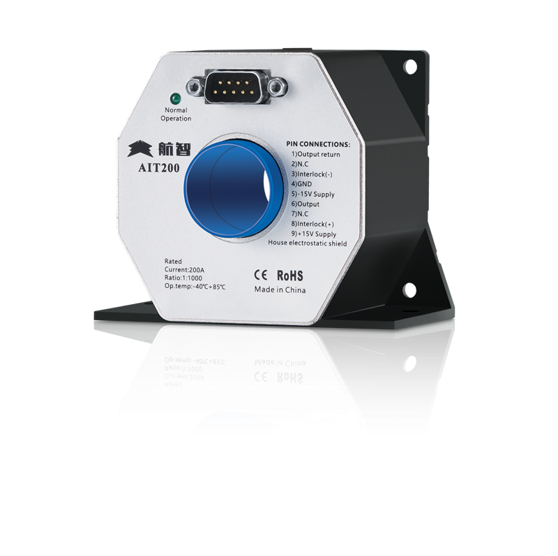 | Precision current transducers AIT 10ppm Ultra-Precision Fluxgate Current Transducer Product Overview: Achieve absolute calibration accuracy with the Hangzhi AIT Series Ultra-Precision Current Transducer. View product → |
 | PRODUCTS DC Current and voltage calibrator The Calmar-S is a volt/mA calibrator designed for: automated calibration and accuracy testing of Electric power meters with pulse output calibration... View product → |
Frequently asked questions
How do you choose the correct reference path for current transducer testing?
Define whether you need ratio, offset, linearity, hysteresis, phase, or overload data, then match the device type, standard, frequency, burden, and environment to the reference instruments.
How do you wire a fluxgate current transducer without creating measurement error?
Follow the transducer’s primary and secondary connections, use the specified burden, control grounding and shielding, and keep high-current and measurement wiring separated.
What should a complete current transducer test matrix include?
Run the required current points across the operating range, include polarity and direction where relevant, allow the system to stabilise, and record frequency, burden, temperature, and supply conditions.
How can you verify whether a 10 ppm current transducer measurement is real?
Check the reference uncertainty, source stability, wiring burden, environmental conditions, repeatability, and calculation method before accepting 10 ppm as a system-level result.
Related product
 | PRODUCTS Energy Meter and Transducer Portable Test System The MTS-MONO-ME 3.12 is a compact portable test system designed for accuracy testing/verification/calibration of smart energy meters and measuring... View product → |