


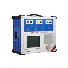
How a Protection class or measurement class Current transformer calibrated?
A current transformer (CT) of protection and measurement class is calibrated using specific procedures to ensure accurate measurement and protection capabilities. Calibration involves comparing the CT's output with a reference standard and adjusting it if necessary. The calibration process typically includes the following steps:
Step 1: Test System Setup
A specialized test system, such as the CT Analyzer is used for current transformer calibration. The CT Analyzer is designed for testing and calibrating CTs according to IEEE and IEC standards The test system is connected to the CT under test, and the necessary measurements and adjustments are made.
Step 2: Ratio Error Test
One of the primary calibration tests is the ratio error test, which determines the accuracy of the CT's turns ratio. This test involves applying known currents to the primary winding of the CT and measuring the resulting secondary current. The measured secondary current is then compared to the expected value based on the CT's turns ratio. Any deviation from the expected value indicates a ratio error, which can be adjusted to bring the CT into calibration.
Step 3: Phase Error Test
The phase error test measures the phase shift between the primary and secondary currents of the CT. This test ensures that the CT provides accurate phase information and is critical for protection applications. The phase error is typically measured at various load levels to assess the CT's performance under different operating conditions.
Step 4: Magnetization Curve Test
The magnetization curve test characterizes the CT's response to different levels of magnetizing current. This test is important for both measurement and protection applications as it determines the accuracy and linearity of the CT's output over a wide range of currents. The test involves applying varying levels of primary current and measuring the secondary current response.
Step 5: Burden Test
The burden test evaluates the accuracy of the CT under different load conditions. This test checks if the CT meets the specified accuracy requirements when connected to its intended load, such as a measurement instrument or protection relay. The test involves applying various burdens to the secondary windings and measuring the resulting secondary current.
Step 6: Calibration Certificate
After completing the calibration process, a calibration certificate is issued, documenting the CT's measured parameters (ratio error, phase error, magnetization curve, etc.) and whether any adjustments were made to bring the CT into calibration. This certificate serves as proof of the CT's accuracy and is typically valid for a specified period.
It's important to note that the specific calibration procedures and requirements may vary depending on the standards and regulations in different countries and industries. Therefore, it is recommended to consult the relevant industry standards, such as IEEE and IEC, for detailed guidelines on calibrating current transformers of protection and measurement class.
Top Supplier of CT/PT analyzer in India
Top Supplier of Variable frequency based CT/PT analyzer
Supplier of economical CT/PT analyzer.